Worm Gear Reducer
90° turn · high reduction ratio · self-locking
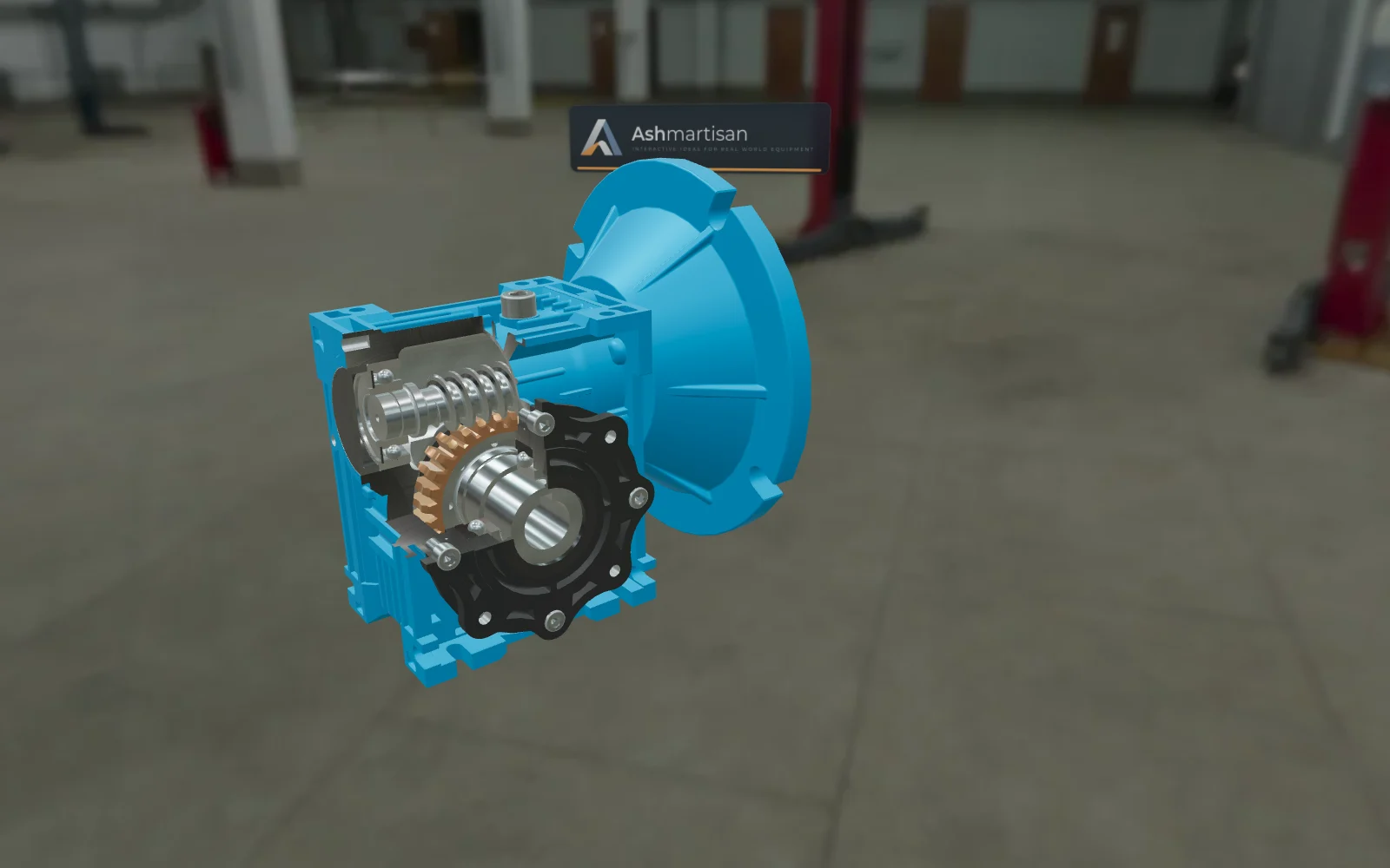
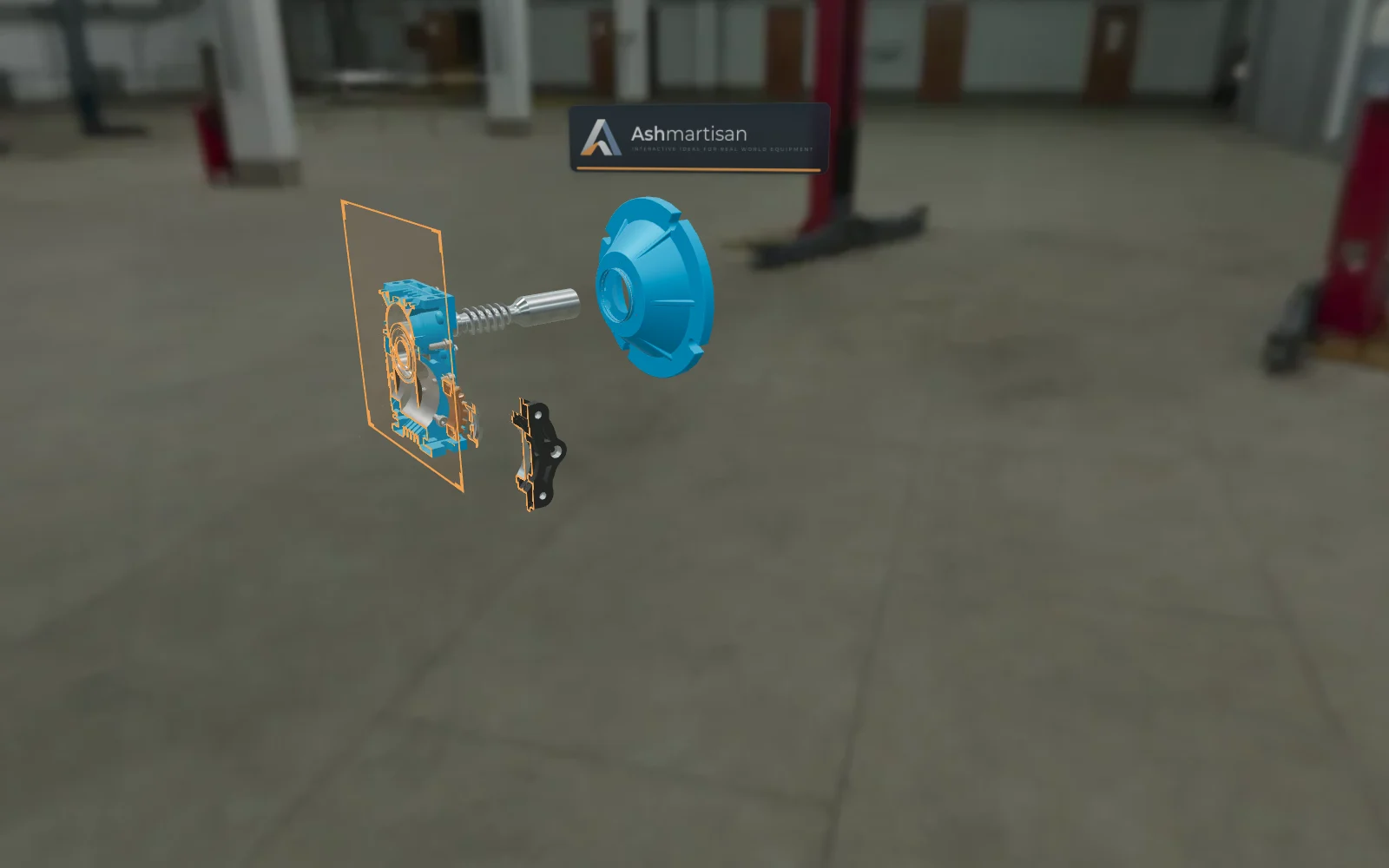
A single-stage worm gear reducer, opened up. Buyers watch the worm drive the bronze wheel through the cut-away housing, follow a walkthrough of how the reduction works, and change the motor speed to see output speed and torque respond.
How it's built
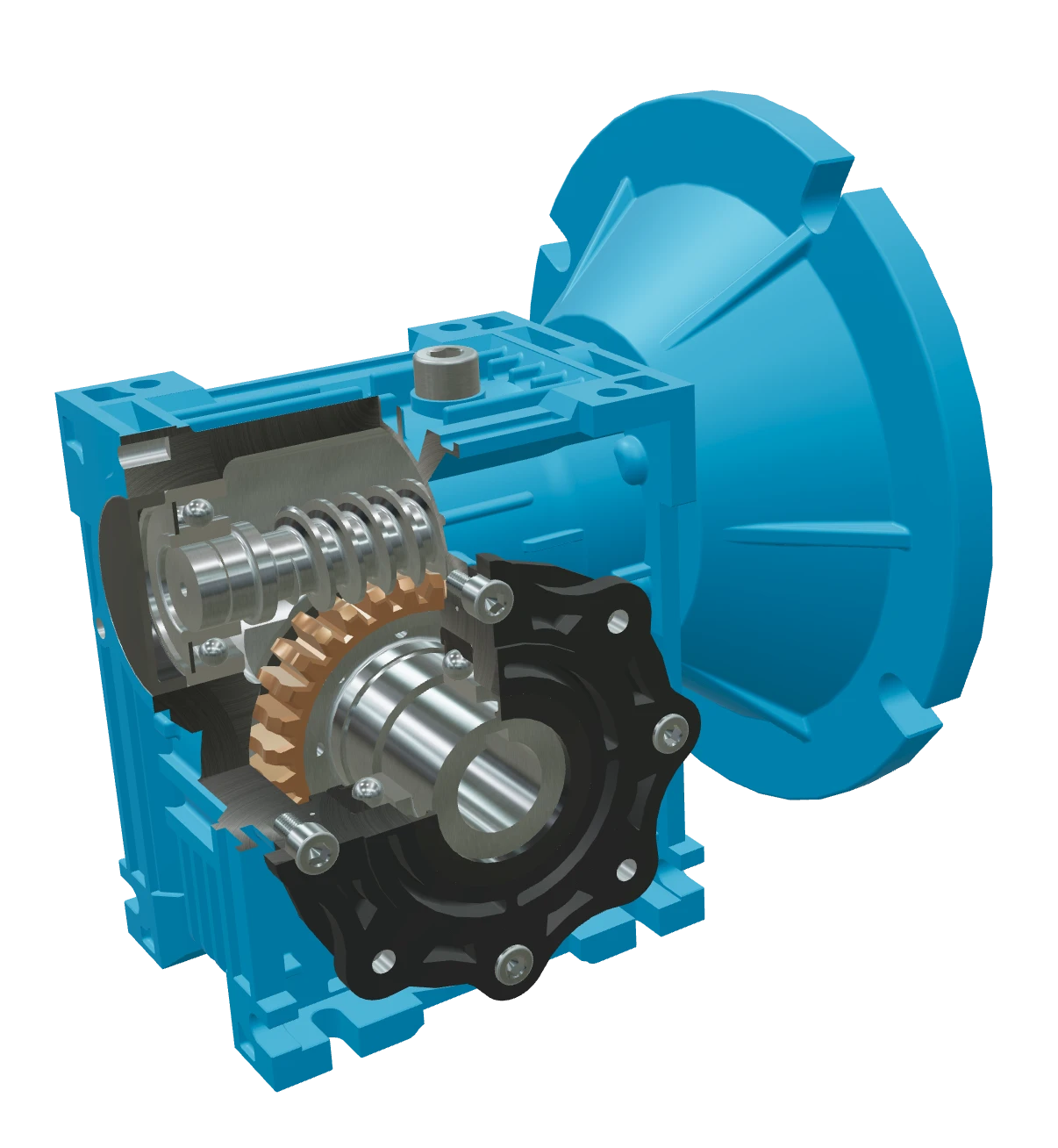 1 Worm (input shaft) Driven by the motor; one turn moves the wheel one tooth 2 Worm wheel Bronze gear in mesh with the worm; its teeth set the ratio 3 Housing Cast casing for the shafts, the oil and the heat 4 Bearings Carry the forces from the mesh at each shaft end 5 Motor flange Standard interface where the motor bolts on 6 Output shaft Delivers the multiplied torque, at 90° to the input
 - 1 Worm (input shaft) Driven by the motor; one turn moves the wheel one tooth
- 2 Worm wheel Bronze gear in mesh with the worm; its teeth set the ratio
- 3 Housing Cast casing for the shafts, the oil and the heat
- 4 Bearings Carry the forces from the mesh at each shaft end
- 5 Motor flange Standard interface where the motor bolts on
- 6 Output shaft Delivers the multiplied torque, at 90° to the input
What the demo shows
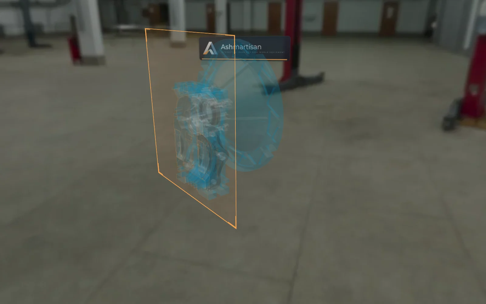
- Cut-away housing The casing is open on one side, so the worm and the wheel are visible in mesh without switching views.
- How the reduction works A captioned walkthrough turns the worm and the wheel together and explains the high ratio and why the drive self-locks.
- Live input speed and power Set the motor speed and power; output speed and torque update while the model runs.
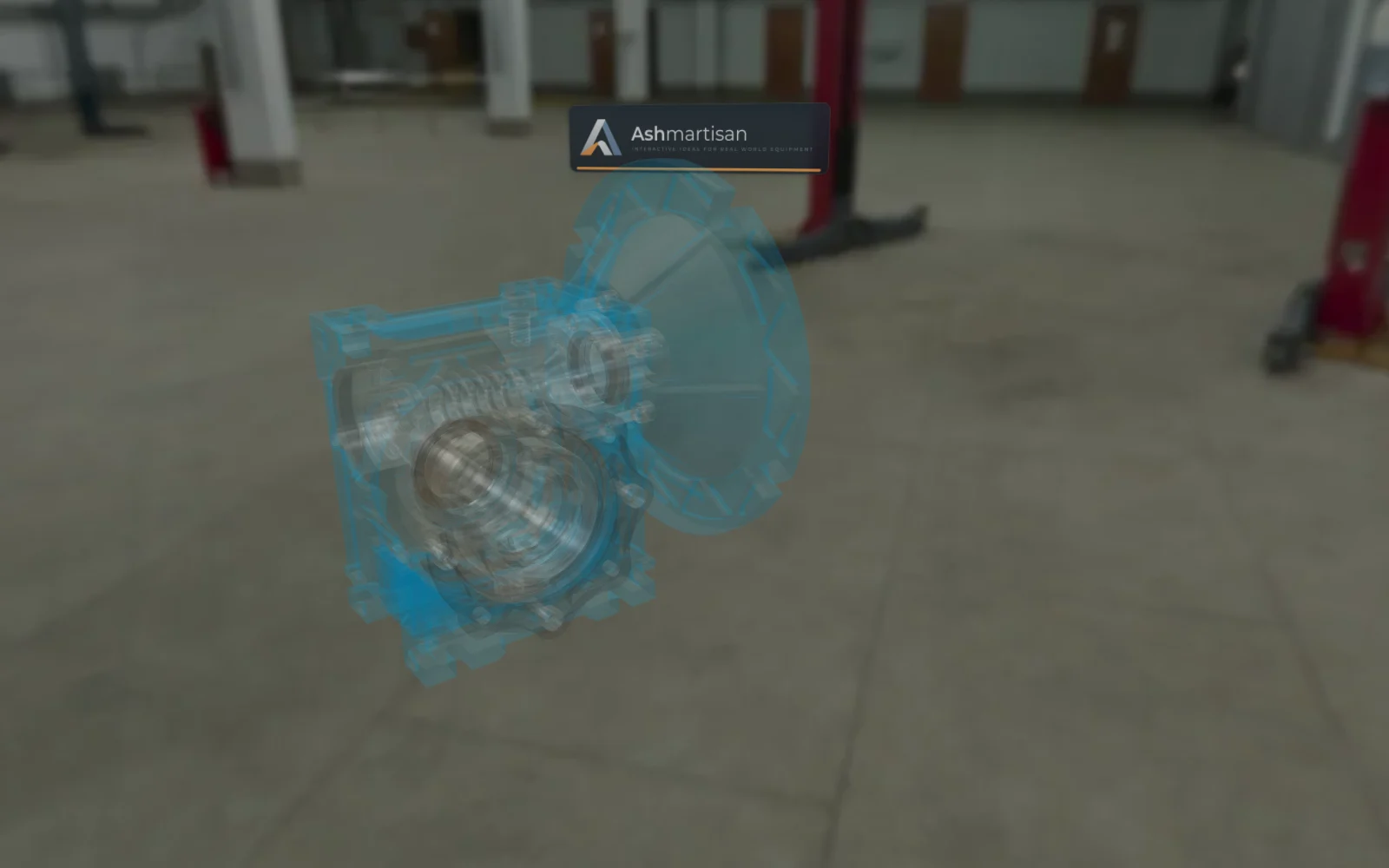
- Exploded view and colours Pull the gearbox apart along its shafts, and switch the flange paint between RAL colours.
Technical data
| Item | Value |
|---|---|
| Transmission | Single-stage worm gear |
| Ratio | approx. 20:1 |
| Input / output | Shafts at 90° |
| Input | Range |
|---|---|
| Input speed (motor) | 0–3000 rpm |
| Input power | 0.5–7.5 kW |
| Part | Property | Value |
|---|---|---|
| Worm (input shaft) | Starts | Single start |
| Material | Hardened alloy steel | |
| Worm wheel | Material | Tin bronze (wear-resistant, low friction) |
| Ratio | ≈ teeth ÷ worm starts | |
| Output shaft | Orientation | 90° to the input shaft |
| Housing | Material | Cast iron / aluminium alloy |
| Motor flange | Mounting | 6 bolts |
| Bearings | Quantity | One at each end of each shaft |
Live read-outs: Output speed · Output torque
Demonstration values for this model, not the data of a specific manufacturer's product.
Want this for your product?
Send us a CAD export or a few photos of one product. We'll show you what its page and live 3D could look like.
Other demo machines
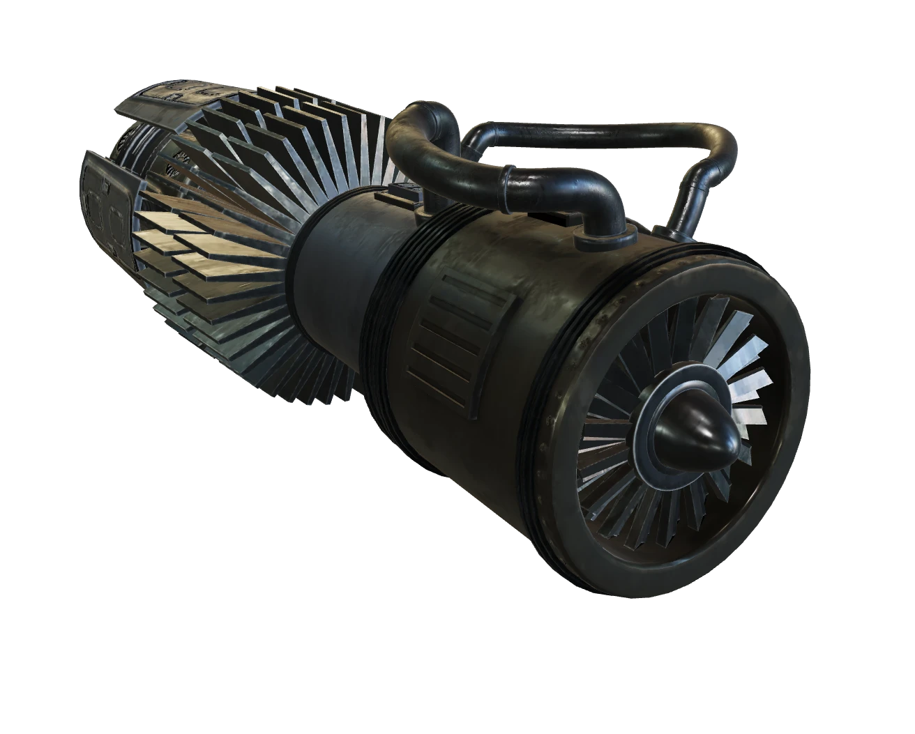 Turbofan Engine Intake → compression → combustion → exhaust
 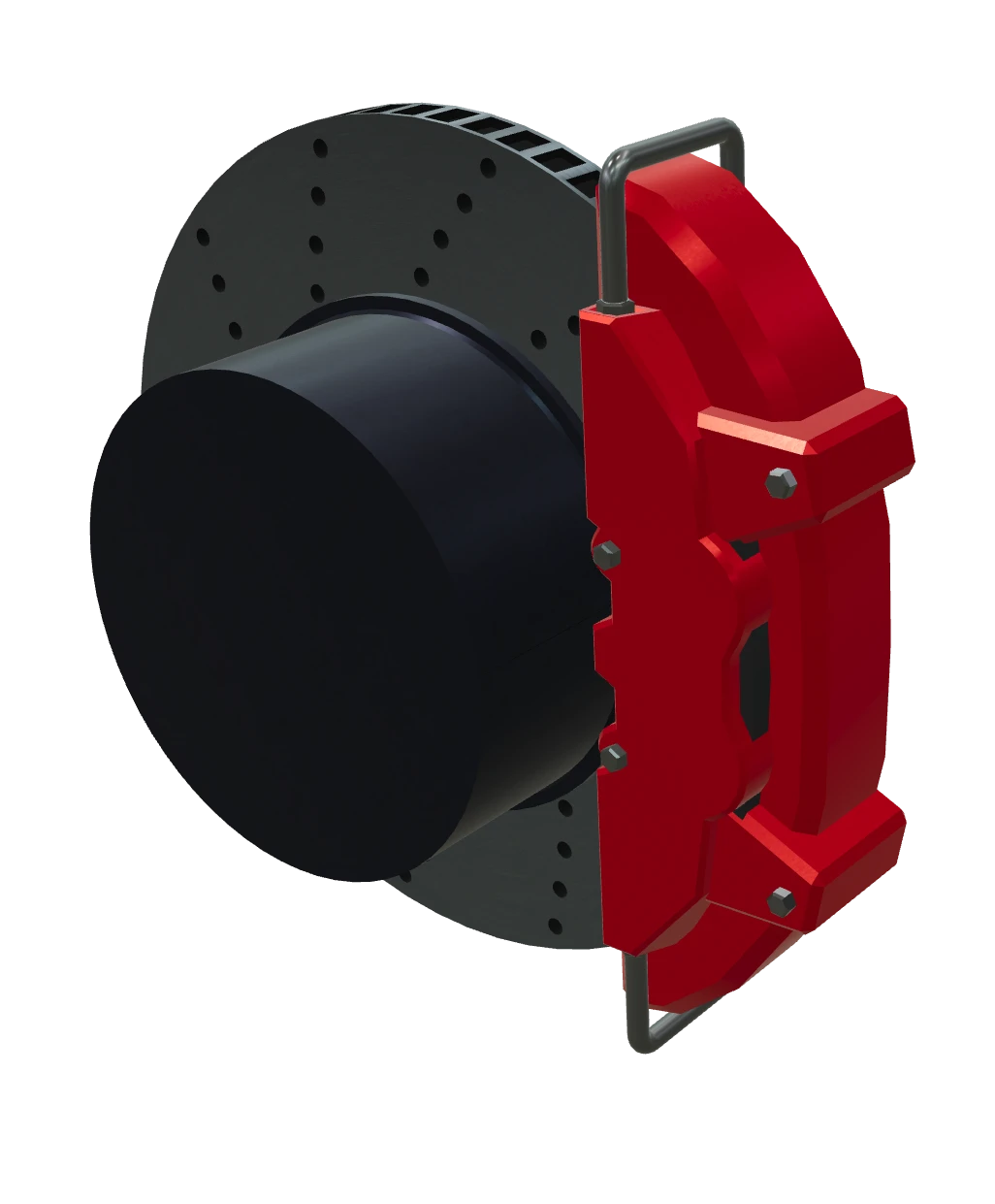 Ventilated Disc Brake Caliper · pads · ventilated disc
 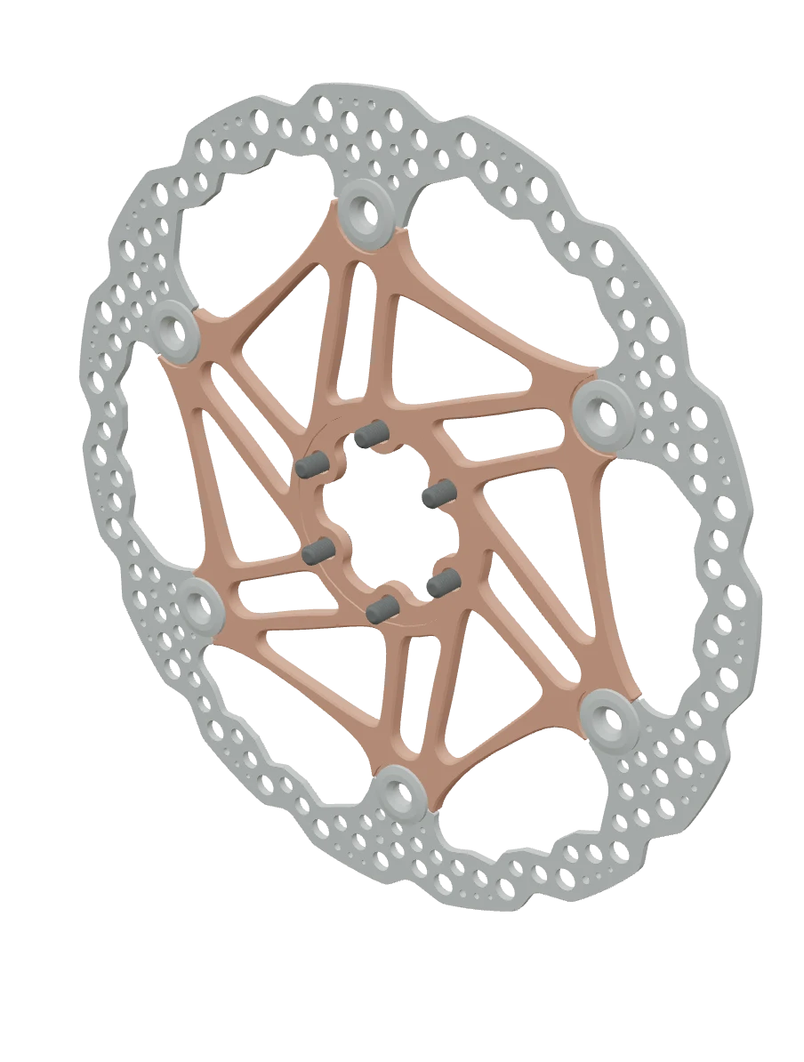 203 mm Floating Brake Rotor Aluminium carrier + steel braking track
 3D model: "Warm Gearbox" by T-FLEX CAD ST (CC BY 4.0)